
Transformers and inductors are important components in power electronic converters. They are used for energy storage, filtering and transformation of voltages and currents.
This article aims to cover the fundamental design considerations that must be addressed. It will however be impossible to cover all the practical aspects, as such this article should only be considered an introduction to the topic.
Transformers

Schematic symbol for a simple transformer. The vertical lines indicate a solid iron core.
Transformers consists of two or more windings that are magnetically coupled towards each other. In order to improve this coupling, it is common for the windings to reside on a core of low reluctance material. I.e. a material with low magnetic resistance.
Transformation ratio
It is well known amongst most electrical engineers that the voltage(and current) transformation ratio equals the turns ratio. This can be understood by realizing that all the turns of the windings around a iron core are exposed to the same magnetic flux.
The voltage induced in a coil is given by Faraday's law of induction as:
\begin{equation}
V = -\frac{\mathrm{d}\Phi}{\mathrm{d}t}
\end{equation}
Hence it can be reasoned, that as long as each coil is exposed to the same magnetic flux change, the total induced voltage is given by:
\begin{equation}
V = - N \cdot \frac{\mathrm{d}\Phi}{\mathrm{d}t}
\end{equation}
Where \(N\) is the number of turns in the coil. When a winding is supplied by a external voltage, this voltage will be divided equally among the turns of the coil. Similarly each turn of a second winding around the same magnetic core, will be exposed to given number of volts per winding turn.
The issue however, and a important parameter when designing a transformer is how many turns to use for each volt.
When the secondary of the transformer is loaded, the increased current causes a voltage drop in the winding resistance. This causes the flux density in the core to be slightly reduced, as there is less magnetizing voltage available. Ideally however the flux density in the core should remain constant regardless of load.
Impedance transformation
It is sometimes useful to consider the transformer as a impedance transforming device.
If the turns ratio of the transformer is given by:
\[ n = \frac{N_2}{N_1} \]
The secondary voltage and current expressed in terms of the primary, is then given by:
\[ V_2 = V_1 \cdot n \]
\[ I_2 = \frac{I_1}{n} \]
The impedance transformation ratio may then be derived as:
\[ Z_2 = \frac{V_2}{I_2} = \frac{V_1 \cdot n}{\frac{I_1}{n}} = n^2 \cdot \frac{V_1}{I_1} = n^2 \cdot Z_1 \]
Hence the impedance transformation ratio, equals the turns ratio squared.
Transformer specifications
Which parameters are important depend on the application, but include:
- Primary voltage and current
- Secondary voltage and current
- Power rating
- Primary inductance
- Leakage inductance
For power transformers the no-load, and short circuit tests are commonly used to obtain the electrical parameters of the transformer.
Equivalent circuit
The equivalent circuit is useful when analyzing the performance of a transformer. It is difficult to obtain a exact model, but this simplified model is sufficient for most transformers. A notable exception however is high voltage transformers used in the power grid, but that is outside the scope of this article.
\(R_1\) and \(X_1\) represents the resistance and reactance in the primary winding, while \(R_2\) and \(X_2\) represents the secondary winding.
\(X_m\) and \(R_m\) represents the magnetizing reactance, and core losses respectively.
In reality the reactances are frequency dependent quantities described by their respective inductances. Additionally the magnetizing inductance is subject to nonlinearity due to the non-linear magnetizing characteristics of the transformer core.
The capacitor \(C_p\) represents the capacitance between the turns in the primary winding, as does \(C_s\) for the secondary winding. \(C_{p-s}\) represents the capacitive coupling between primary and secondary winding. The capacitances are often neglected, especially in power transformers.
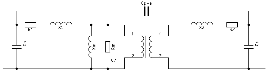
Transformer equivalent circuit
The exact same circuit may be(and often is) used for analyzing three phase transformers. The only difference is that the relation between phase and line quantities must be considered.
No load test
The no load test is performed by applying the rated voltage(at rated frequency) to the primary winding, while the secondary is open circuit. The voltage and current(and their displacement) is measured.
The power consumed it no load condition, is referred to as the no-load losses, and consists mainly of hysteresis and eddy current losses.
\begin{equation}
P_0 = P_E + P_H
\end{equation}
It is computed by considering only the active part of the current, i.e.:
\begin{equation}
P_0 = V_N \cdot I_0 \cdot \cos(\phi_0)
\end{equation}
Where \(\cos(\phi_0)\) is the displacement power factor.
The equivalent no load impedance is given as:
\begin{equation}
Z_m = R_m + jX_m
\end{equation}
Where the no load resistance and impedance is given by equation \ref{eq:no-load-resistance} and \ref{eq:no-load-impedance} respectively.
\begin{equation}
R_m = \frac{V_N^2}{P_0}
\label{eq:no-load-resistance}
\end{equation}
\begin{equation}
Z_m = \frac{V_N}{I_0}
\label{eq:no-load-impedance}
\end{equation}
The test could just as easily be conducted on the secondary side of the transformer, the only difference will be that the computed impedances will be referred to that side.
By measuring the secondary voltage during no load test, the turns ratio may also be determined.
Short circuit test
The short circuit test is performed by short circuiting the secondary winding, and applying the sinusoidal voltage required to obtain the rated current in the primary. As with the no load test, the current, voltage and displacement power factor is measured.
\begin{equation}
P_{sc} = V_{sc} \cdot I_{N} \cdot \cos(\phi_{sc})
\label{eq:sc-power}
\end{equation}
The equivalent resistance referred to the high voltage side is given by:
\begin{equation}
R_{e} =\frac{V_{N}^2}{P_{sc}}
\label{eq:sc-resistance}
\end{equation}
And the equivalent impedance is given by:
\begin{equation}
Z_{e} = \frac{V_{sc}}{I_{N}}
\label{eq:sc-impedance}
\end{equation}
Determine the volt/turn constant
If you intend to replicate an already existing transformer, this test may be useful.
Add a small winding on the core, on top of the existing windings. The number of turns is not critical as long as you keep track of them. Apply nominal voltage to the primary(or secondary), and measure the voltage induced in the test winding. Divide this voltage by the number of turns in the test winding to obtain the volt/turn constant.
By knowing the nominal voltages for the transformer, you can calculate the number of turns in each winding.
\begin{equation}
N = \frac{V_N}{K_{emf}}
\end{equation}
Determine frequency response
The lower frequency limit of the transformer is governed by the primary inductance. As the frequency decreases, so does the reactance, and thus the transformer will load down the driving circuit. The upper frequency response is governed by the leakage inductance. This inductance appears to be in series with the transformer, and as the frequency increases it will act as a higher impedance.
The frequency response is normally not important for power transformers running at line frequency. It is however very important in transformers intended to carry signals at a range of frequencies.
This test is best performed using a network analyzer, and obtaining the bode plot. If however you do not have access to such equipment, it is also possible to use a signal generator and a voltmeter/oscilloscope.
Apply a constant amplitude, variable frequency sinusoidal voltage to the primary and measure the secondary amplitude. The attenuation in dB is given by:
\begin{equation}
dB = 20\cdot \log(\frac{V_{out}}{V_{in}})
\end{equation}
E.g. when the primary voltage is \(1\;V\), the relation between \(-3dB\) attenuation, and the secondary voltage, is:
\begin{equation*}
-3dB \approx 20\cdot \log(\frac{0.707}{1})
\end{equation*}
For audio application you should probably consider to use \(-1dB\) as the design criteria however.
There are some (relatively) cheap network analyzers available for low frequency testing. I will not recommend any specific model or manufacturer, but if (audio)transformers is your thing, it might be worth investigating further.
Impedance transformers
Transformers will sometimes be specified as having a certain impedance transformation ratio. A common example is the \(600:600 \Omega\) transformation ratio often seen in audio transformers. This may be a bit confusing to newcomers, as there is no inherent impedance associated with an ideal transformer. The voltage and current transformation ratio is \(1:1\) for this example. A \(600:1200 \Omega\) transformer would have a \(1:2\) transformation ratio.
The frequency response of a audio transformer is usually specified as the \(-3dB\) limit referred to \(1000\;Hz\). I.e. the frequencies where the voltage level has dropped to \(70.7\%\) of the voltage level at \(1000\;Hz\).

Transformers: More than Meets the Eye.
The reason for specifying a impedance, is that the transformer is designed to have a adequate frequency response down to a load of \(600\; \Omega\). The inductive reactance of the winding must be higher than (or equal to) \(600\; \Omega\) at the lowest frequency of interest. The required winding inductance is thus given by:
\begin{equation}
L = \frac{Z}{2 \pi f}
\end{equation}
For the audio transformer used as a example, with a lower frequency (-3dB) limit of \(50Hz\), the required inductance will be given as:
\begin{equation*}
L = \frac{600}{2 \pi 50} = 1.9H
\end{equation*}
Sometimes the -1dB response is used. This gives us the following inductance:
\begin{equation*}
L = \frac{600}{\pi 50} = 3.8H
\end{equation*}
Further, if the power rating for the transformer is given, the voltage rating is given by the nominal load as:
\begin{equation}
V = \sqrt{P \cdot Z}
\end{equation}
Again, for our example (which has a rating of \(0.25 \; W\)), this will evaluate to:
\begin{equation*}
V = \sqrt{0.25 \cdot 600} = 12.3 \;V
\end{equation*}
Transformer design
In this design introduction only single phase transformers are considered. The basic principles however, are the same for multiphase designs.
The first step in the design procedure for the transformer is determining and assembling the design inputs. These normally consists of:
- Rated primary voltage and current
- Operating frequency
- Transformation ratio, i.e. turns ratio
- Thermal constraints, i.e. maximum body and ambient temperature
Magnetic design
One of the most important parameters imposing limitations on the volts per turn for line frequency application, is the maximum flux density in the core of the transformer. Typical values are from \(1\) to \(1.7\) Tesla.
As the frequency of operation increases(above a few hundred hertz), the core losses will be the limiting factor. The change in flux is the major source for core losses, and thus the flux must be limited in accordance with the manufacturers specification for the given core and frequency. Typical values are in the range of \(0.2 - 0.05T\), but you really have to check the datasheet.
The magnetic flux, measured in weber, in a loop of wire is given by:
\begin{equation}
\Phi = B \cdot A = V \cdot t
\end{equation}
Where \(\Phi\) is the magnetic flux, \(B\) is the magnetic flux density, and \(A\) is the area surrounded by the coil. \(V\) is the voltage applied to the loop, and \(t\) is the duration(time).
By adding more turns to the coil, the applied voltage vil be divided evenly among the turns, hence:
\begin{equation}
\Phi = \frac{V \cdot t}{N}
\end{equation}
Where \(N\) is the number of turns. Another way to look at it is that the increased number of turns increases the inductance, hence the current decreases (and flux depends on current).
\begin{equation}
\Phi = L \cdot I
\label{eq:inductor-flux}
\end{equation}
The voltage induced in a coil of wire is given by the differential equation:
\begin{equation}
V = -L \cdot \frac{\mathrm{d}i}{\mathrm{d}t}
\label{eq:inductor-voltage}
\end{equation}
Hence the inductance of a coil is given by:
\begin{equation}
L = \frac{V \cdot t}{I}
\label{eq:inductance-definition}
\end{equation}
Where \(I\) is the current through the wire. Equation \eqref{eq:inductance-definition} may be derived from both equation \eqref{eq:inductor-flux} and \eqref{eq:inductor-voltage}. Take your pick.
Leakage inductance
The leakage inductance is caused by the parts of the magnetic flux that does not link the primary and secondary windings.
In most transformers the leakage inductance should be minimized. A unfavorable leakage inductance may cause overvoltages in a switching power converter, adding additional requirement to the snubber circuits.
A notable exception to this rule is microwave oven transformers, where magnetic shunts are added in order to increase the leakage inductance. The reason for these shunts is that the transformer is intended to drive a capacitive load. The secondary of a microwave oven transformer is typically connected to a voltage doubler, and the capacitive reactance of this doubler should ideally match the inductive reactance of the transformer.
Exact calculation of the leakage inductance is challenging, but approximate analytical formulas are available for various cores and winding configurations. For a rectangular shaped(E) core, and no interleaving of the windings, the leakage inductance may be approximated by:
\begin{equation}
L_L \approx \frac{\mu_0 N_{p}^2 l_w b_w}{3 h_w}
\end{equation}
Where \(N_{p}\) is the number of primary turns, \(l_{w}\) is the mean length of a winding turn, and where \(b_{w}\), and \(h_{w}\) is the width and height of the winding window.
For split(interleaved) winding arrangements, the leakage inductance may be approximated by:
\begin{equation}
L_L \approx \frac{\mu_0 N_{p}^2 l_w}{p^2 h_w} \left( \frac{b_{Cu}}{3} + b_i \right)
\end{equation}
Where \(p\) is the number of interfacing sections, \(b_{Cu}\) is the width of the copper in the window of the windings, and \(b_{i}\) is the interwinding insulation thickness
Design example
Suppose you want to design a power transformer operating at a primary voltage of 230V RMS, at a frequency of 50Hz.
Normally we would have a given power requirement, putting constraints on the selection of iron core, but suppose for this example that we already have a core. Although this assumption may sound strange, it is not uncommon for hobbyists to use(or at least try to use) a core they happen to have in their junkbox.
The core for our example has a cross sectional area of 45 x 30mm, i.e. \(0.00135m^2\), and a maximum flux density of \(1.3 T\).

The transformer core used in the example.
The maximum flux in the core is then calculated as:
\[ \Phi = B \cdot A = 1.3 \cdot 0.00135 = 0.00176 Wb \]
The maximum flux change in the core however is double, as the core may be magnetized in both directions, i.e.: \(0.00352 Wb\).
The number of turns required to obtain this flux is given by:
\begin{equation*}
N = \frac{V \cdot t}{\Phi}
\end{equation*}
Where \(V\) is the average voltage applied to the winding.
If the voltage is given by \(v(t) = V_p \cdot \sin(\omega t) \), then the average may be derived as follows:
\[ V_{avg} = \frac{1}{\pi} \int_0^{\pi} V_p \cdot \sin(\omega t) \mathrm{d}t \]
\[ V_{avg} = \frac{V_p}{\pi} \left[ -\cos(\omega t) \right]_0^{\pi} \]
\( \cos(0) = 1 \) and \( \cos(\pi) = -1 \), hence:
\[ V_{avg} = \frac{2 V_p}{\pi} \]
For our example, the average voltage is computed as:
\[ V_{avg} = \frac{2 \cdot 230 \cdot \sqrt{2}}{\pi} = 207 V \]
The required number of turns is computed as:
\[ N = \frac{207 \cdot 0.01}{0.00352} = 588\]
Hence, expressed in terms of RMS, we have 0.39 volts per turn, or 2.56 turns per volt. For the secondary the required number of turns is then simply calculated by multiplying 2.56 by the desired voltage.
E.g. if the required secondary voltage is \(18\;V\) (which may be suitable for a 12V linear regulated supply), the required number of turns will be:
\begin{equation*}
2.56 \cdot 18 = 46
\end{equation*}
Power capability
Computing the power is not as straight forward as computing the required number of turns. For small transformers however, it is usually safe to make some assumptions based on experience. One of those assumptions is that a efficiency of 90%, i.e. a loss of 10% is acceptable without the risk of overheating the transformer.
The primary limiting factor is the heating of the windings, that is the \( I^2 R \) losses.
For a given core, there will be a given window available for the windings. The core used in the winding example has a window of 45 x 15mm. Additionally the distance around the core is \( 45 + 45 + 30 +30 = 150mm \).
It is often assumed a fill factor of 40%, that is about 40% of the core window is used for copper, the rest being used for insulation and air. This gives us a copper area of: \( 6.75 \cdot 0.4 = 2.7 cm^2 \). The primary winding is given half of this area, i.e. the wire cross sectional area is given as:
\[ A = \frac{1.35\cdot 10^{-4}}{588} = 0.23mm^2 \]
Copper has a resistivity \( \rho = 1.68\cdot 10^{-8} \Omega m \), and the resistance of the winding is given by:
\[ R = \frac{ \rho \cdot l}{A} \]
If the average turns length is 200mm, the total length is about 117.6m. The winding resistance is then given as:
\[ R = \frac{ 1.68\cdot 10^{-8} \cdot 117.6}{2.3\cdot10^{-7}} = 8.59 \Omega\]
As previously stated we will allow a power loss of 10%, i.e. the primary winding will be allowed a loss of 5%.
\[ P_{loss} = \frac{V^2}{R} = \frac{230 \cdot 0.05}{8.59} = 15.4W \]
The rated input power of the transformer is then computed as:
\[ P = \frac{15.4}{0.1} = 154 W \]
A note about DC current
DC current in a transformer is normally not a good thing. It will not contribute to the power delivered by the transformer, but it will contribute to the magnetic flux in the core. This means that the core will be closer to saturation. If the transformer is designed to be at the edge of saturation without DC current, it will saturate.
If you intend to have DC current in the transformer, you should apply the same design constraints as when designing a inductor intended for DC. Typically this means adding a air gap to the core, in order to reduce the effective permeability.
Inductors
Inductance is a parameter of any electric network describing it's ability to resist change in current.
\begin{equation}
\text{EMF} = -L\frac{\mathrm{d}i}{\mathrm{d}t} \Rightarrow L = - \text{EMF} \frac{\mathrm{d}t}{\mathrm{d}i}
\end{equation}
Energy storage
Energy storage is usually not desired in transformers, it is however often the primary purpose of a inductor. It is among other things used in the buck-boost converter, and the flyback converter.
The energy stored in a inductor is given by:
\begin{equation}
E = \frac{1}{2} \cdot L \cdot I^2
\end{equation}
Where \(I\) is the magnetizing current. I.e. when computing the energy storage in a transformer, it will be less that the total current.
Quality factor
The quality factor of a inductor describes the device in relation to a ideal component. It is of particular importance in RF applications.
The quality factor of a inductor is given by:
\begin{equation}
Q_L = \frac{X_L}{R_L} = \frac{2\pi f L}{R_L}
\end{equation}
Hence the quality factor depends on the frequency under which the inductor is used. It is important to note that due to the skin-effect, the winding resistance \(R_L\) is also a function of frequency.
Inductor design example
Suppose we want to design a switching converter operating at \(100kHz\), with a 30% charge cycle. Our core has a cross sectional are of \(3cm^2\), and a maximum flux density of \(0.05T\) at the frequency in question.
The maximum flux in the core is given as:
\[ \Phi = B \cdot A = 0.05 \cdot 3\cdot 10^{-4} = 15\mu Wb \]
If the input voltage is 230V RMS rectified, i.e. 325V DC, the required number of primary turns is given as:
\[ N = \frac{V \cdot t}{\Phi} = \frac{325 \cdot 3\cdot10^{-6}}{15\cdot10^{-6}} = 65 \]
The energy stored in the core depends on the inductance. Typically the manufacturer will supply a number \(A_L\), which when multiplied by the turns ratio squared, gives us the inductance. The inductance of a toroid core is approximately given by:
\[ L \approx \frac{\mu N^2 A}{2\pi r} \]
Where \(A\) is the cross sectional area of the core, and \(r\) is the radius to the centerline of the core.
As can be seen, all factors except the number of turns, are constants for the given core. Similar equations may be derived for different core shapes.
Suppose for our example that \(A_L = 7\mu H / N^2\). The inductance of the primary winding will be approximately \( 29.6mH \). The current will ramp up linearly, with a peak current at the end of the on-cycle given by:
\[ I = \frac{V \cdot t}{L} = \frac{325 \cdot 3\cdot10^{-6}}{0.0296} = 0.033A \]
The energy stored in the core at each switching interval is then given as:
\[ E = V \cdot I \cdot t = 325 \cdot \frac{0.033}{2} \cdot 3\cdot10^{-6} = 16 \mu J\]
As the frequency is \(100kHz\), we will have \(100000\) such intervals each second. Hence the total energy transferred each second is given as:
\[ E = 16\cdot 10^{-6} \cdot 100000 = 1.6J/s = 1.6W\]
This power may seem somewhat low for a core of \(3cm^2\) cross sectional area. The best way to increase the power capability is to reduce the inductance, and hence increase the current in the core. Remember that the power depends on the current squared.
By introducing a airgap in a magnetic core, the effective permeability will decrease, and hence the \(A_L\)-value will also decrease.
The energy stored in the core may be extracted by a second winding on the same core, as in the flyback topology. Alternatively it may be used by connecting the inductor to a different circuit once it is charged, as in the buck/boost topologies.
Toroids
Toroidal cores can be divided into two main categories, depending on the material from which they are made. Ferrite, and Iron powder cores.
Ferrite has the highest permeability, but it is not suitable for high frequencies. Additinally, as we have seen, high permeability is not always an advantage.
A useful website with specifications for various toroidal cores is located at: http://toroids.info/
As previously mentioned the flux density must be limited to avoid saturation of the core. For ferrite toroidal cores this imposes the constraint:
\begin{equation}
\frac{V}{2 f N A} \le 0.3
\end{equation}
Where \(N\) is the number of winding turns, and \(A\) is the cross sectional area of the core.